

How Does Changing The Size Of Gears Change The Output Of A Gear Train
AB-024
Introductory Gear Equations
At that place are a couple of ways to become the exact speed you demand on a motor, although we'd similar to think that we provide a adequately comprehensive range of gear motors. If you can't find an off the shelf solution, we're always happy to help hash out custom variations or encoder / PID solutions with y'all – only drop our engineers a line.
For chop-chop experimenting or prototyping, you may wish to build your ain cheap gear chain. Here we'll take a expect at a couple of basic calculations to go y'all started and which should provide an easy reference to return to as yous need.
Relationship Between 2 Gears
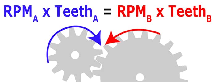
When ii gears are continued (nosotros say 'in mesh') the speed relationship is very simple and is dependent only on the number of teeth in each gear. That is, the ratio of teeth is equal to the inverse ratio of speed. Information technology is easier to sympathise when written equally an equation:𝑇𝑒𝑒𝑡ℎ𝐴𝑇𝑒𝑒𝑡ℎ𝐵=𝑅𝑃𝑀𝐵𝑅𝑃𝑀𝐴
Or you may observe it easier to retrieve that the product of the number of teeth and speed equal between the gears, i.e. the number of teeth times the speed of gear A will equal the number of teeth times the speed of gear B:𝑅𝑃𝑀𝐴×𝑇𝑒𝑒𝑡ℎ𝐴=𝑅𝑃𝑀𝐵×𝑇𝑒𝑒𝑡ℎ𝐵
Whichever mode is easier for you to recollect, we tin calculate any i variable assuming nosotros take the other iii. Often, we may already have a motor and desired output speed – using the beginning equation nosotros tin can detect the required ratio of teeth on the gears.


Become in touch
Speak to a member of our team.
Motor catalogue
Looking for our products?
Reliable, cost-constructive miniature mechanisms and motors that meet your application demands.
For example, our 108-106 has a no load speed of 18,000 RPM at 3V. Let'due south say we wanted to reduce this to under 5,000 RPM:𝑇𝑒𝑒𝑡ℎ𝐴𝑇𝑒𝑒𝑡ℎ𝐵=𝑅𝑃𝑀𝐵𝑅𝑃𝑀𝐴𝑇𝑒𝑒𝑡ℎ𝐴𝑇𝑒𝑒𝑡ℎ𝐵=five,000𝑅𝑃𝑀18,000𝑅𝑃𝑀𝑇𝑒𝑒𝑡ℎ𝐴𝑇𝑒𝑒𝑡ℎ𝐵=0.277778
OR𝑇𝑒𝑒𝑡ℎ𝐵𝑇𝑒𝑒𝑡ℎ𝐴=3.6
This means our second gear needs to have at least 3.vi times as many teeth every bit our outset gear. If gear A has x teeth, gear B must have at least 36. Y'all may have to compromise when it comes to gear selection, not every value of teeth is available and you may find even numbers more common than odd.
A quick delve into a handful of our role supply returns the following sizes:
- threescore teeth
- 42 teeth
- thirty teeth
- xvi teeth
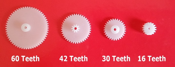
Using the 16 tooth size as gear A and the threescore tooth size as gear B gives us a ratio of iii.75 between the gears. This equates to 4,800 RPM when used with the 108-106. Note that due to the nature of the mode the gears mesh, they will plow in reverse directions.
If nosotros needed to reduce the output speed fifty-fifty farther, say close to one,000 RPM, we would demand to increase the gearing ratio – but how do we overcome size restrictions? Virtually applications are limited in infinite, and the more teeth you require the greater the bore of the gear.
Adding In Gears
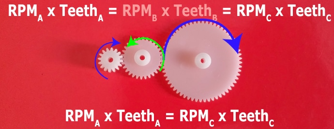
Your first instinct may be to only add a tertiary gear, but as we will see that this has no effect on the output speed. Retrieve when ii gears are in mesh:𝑅𝑃𝑀𝐴×𝑇𝑒𝑒𝑡ℎ𝐴=𝑅𝑃𝑀𝐵×𝑇𝑒𝑒𝑡ℎ𝐵
And so the relationship between our third and second gear is given every bit:𝑅𝑃𝑀𝐵×𝑇𝑒𝑒𝑡ℎ𝐵=𝑅𝑃𝑀𝐶×𝑇𝑒𝑒𝑡ℎ𝐶
Therefore:𝑅𝑃𝑀𝐴×𝑇𝑒𝑒𝑡ℎ𝐴=𝑅𝑃𝑀𝐵×𝑇𝑒𝑒𝑡ℎ𝐵=𝑅𝑃𝑀𝐶×𝑇𝑒𝑒𝑡ℎ𝐶𝑅𝑃𝑀𝐴×𝑇𝑒𝑒𝑡ℎ𝐴=𝑅𝑃𝑀𝐶×𝑇𝑒𝑒𝑡ℎ𝐶𝑇𝑒𝑒𝑡ℎ𝐴𝑇𝑒𝑒𝑡ℎ𝐶=𝑅𝑃𝑀𝐶𝑅𝑃𝑀𝐴
The relationship between the speed of the input and the speed of the output is just dependant upon the ratio of teeth between the input and the output gears. Notwithstanding, the addition of the second gear does ensure the input and output gears turn in the same direction.
Compound Gears
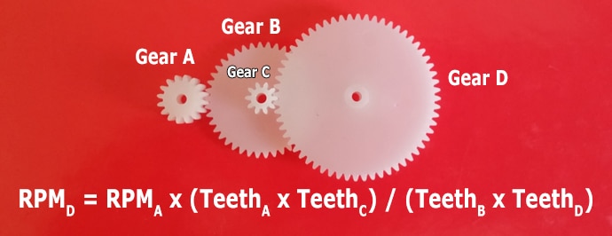
This is overcome past using what is known equally a compound gear, where a single gear has 2 dissimilar sets of teeth:

With the compound gear the speed is preserved between the gear's two sets of teeth. Using a compound gear, lets look at how our speed and teeth relationship is changed. To explain, we volition treat the compound gear as two divide gears (B and C) that are forced to the same speed. We now have two separate meshes:𝑅𝑃𝑀𝐴×𝑇𝑒𝑒𝑡ℎ𝐴=𝑅𝑃𝑀𝐵×𝑇𝑒𝑒𝑡ℎ𝐵
and𝑅𝑃𝑀𝐶×𝑇𝑒𝑒𝑡ℎ𝐶=𝑅𝑃𝑀𝐷×𝑇𝑒𝑒𝑡ℎ𝐷
However the speeds of gear B and gear C are equal, nosotros'll rename information technology 𝑅𝑃𝑀𝐵𝐶 to clarify:𝑅𝑃𝑀𝐴×𝑇𝑒𝑒𝑡ℎ𝐴=𝑅𝑃𝑀𝐵𝐶×𝑇𝑒𝑒𝑡ℎ𝐵𝑅𝑃𝑀𝐵𝐶×𝑇𝑒𝑒𝑡ℎ𝐶=𝑅𝑃𝑀𝐷×𝑇𝑒𝑒𝑡ℎ𝐷
Nosotros tin rearrange each equation to give a value for 𝑅𝑃𝑀𝐵𝐶:𝑅𝑃𝑀𝐵𝐶=𝑅𝑃𝑀𝐴×𝑇𝑒𝑒𝑡ℎ𝐴𝑇𝑒𝑒𝑡ℎ𝐵𝑅𝑃𝑀𝐵𝐶=𝑅𝑃𝑀𝐷×𝑇𝑒𝑒𝑡ℎ𝐷𝑇𝑒𝑒𝑡ℎ𝐶𝑅𝑃𝑀𝐷×𝑇𝑒𝑒𝑡ℎ𝐷𝑇𝑒𝑒𝑡ℎ𝐶=𝑅𝑃𝑀𝐴×𝑇𝑒𝑒𝑡ℎ𝐴𝑇𝑒𝑒𝑡ℎ𝐵
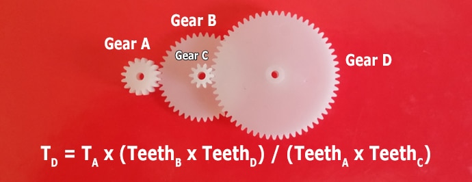
Our output speed is therefore:𝑅𝑃𝑀𝐷=𝑅𝑃𝑀𝐴×𝑇𝑒𝑒𝑡ℎ𝐴×𝑇𝑒𝑒𝑡ℎ𝐶𝑇𝑒𝑒𝑡ℎ𝐵×𝑇𝑒𝑒𝑡ℎ𝐷
Teeth A and C tin can be thought of equally transmitting ability, i.e. these are forcing teeth B and D to rotate. You can think of the output speed as the input speed times the product of transmitting teeth divided by the product of receiving teeth:𝑂𝑢𝑡𝑝𝑢𝑡𝑆𝑝𝑒𝑒𝑑=𝐼𝑛𝑝𝑢𝑡𝑆𝑝𝑒𝑒𝑑×𝑃𝑟𝑜𝑑𝑢𝑐𝑡𝑜𝑓𝑇𝑟𝑎𝑛𝑠𝑚𝑖𝑡𝑡𝑖𝑛𝑔𝑇𝑒𝑒𝑡ℎ𝑃𝑟𝑜𝑑𝑢𝑐𝑡𝑜𝑓𝑅𝑒𝑐𝑒𝑖𝑣𝑖𝑛𝑔𝑇𝑒𝑒𝑡ℎ
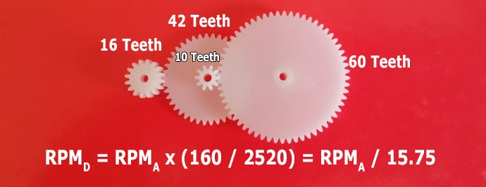
Back to our example, it just so happens the 42 tooth gear happens to be a compound gear with a 10 tooth secondary gear. We'll continue to use the smallest gear to drive and the biggest as the final stage to maximise our overall gearing. And then our setup now looks equally follows:
- Gear A: 16 teeth
- Gear B: 42 teeth (chemical compound with Gear C)
- Gear C: 10 teeth (compound with Gear B)
- Gear D: sixty teeth
Still using the 108-106 at 18,000 RPM, what would we wait the new output speed to exist?𝑅𝑃𝑀𝐷=𝑅𝑃𝑀𝐴×𝑇𝑒𝑒𝑡ℎ𝐴×𝑇𝑒𝑒𝑡ℎ𝐶𝑇𝑒𝑒𝑡ℎ𝐵×𝑇𝑒𝑒𝑡ℎ𝐷𝑅𝑃𝑀𝐷=eighteen,000×sixteen×1042×lx𝑅𝑃𝑀𝐷=1,143𝑅𝑃𝑀
Still a little above our target, only nosotros've reduced the the output speed by ~94% – which is a significant reduction from only a few gears!
Once we empathise how the speed is reduced through the gear chain, calculating the transfer of torque is simple: it is the inverse of the speed ratio.
As the output speed of the gear chain decreases, the system can deliver more torque. If y'all browse our product catalogue, you lot can see that for like motors (for example our 212-4XX) as the Gear Ratio increases, the Rated Torque increases, and the Rated Speed decreases.
An important note is to remember that the speed depends on the level of required torque. So a motor's output speed is always at a specified level of torque. The Rated Speed is at the Rated Torque, and other values can be read from the Typical Performance characteristics graphs.
If the load is constant, a meliorate mode of thinking nigh it is not to consider the torque as an output of the motor but every bit an input to the organisation. With our known load at the output gear, we actually piece of work backwards to find what load motor is seen by the motor. From there we can read the Typical Operation Characteristics and approximate the speed of the motor and other details such as the current draw.
Alternatively, if you want to calculate the maximum torque a motor tin deliver with its new gear chain, you would have the Stall Torque value from the motor'southward datasheet and utilize the relationship below to calculate the output torque. This is useful if yous don't intendance well-nigh speed, you just want to brand sure the load is moved (or accept a broad tolerance for your speed).
There are a few caveats with this, showtime at stall the speed is plain 0 RPM – simply using a 'shut to stall' speed of 1 RPM avoids divisions/multiplications by nix. Secondly, sometimes stall torques are estimates – a motor doesn't always steadily subtract to 0 RPM and so it would exist wise to use a margin of error. Lastly, once a motor is running it tin handle a greater torque load than when it's starting time starting to turn. That means the Stall Torque is probable to be a greater value than the maximum starting torque.
We'll consider each of these scenarios, just first, let'due south review the relationship. For two gears in mesh, we're essentially replacing the Teeth with the Torque (pull the teeth out!):
𝑇𝐴𝑇𝐵=𝑅𝑃𝑀𝐵𝑅𝑃𝑀𝐴
or𝑅𝑃𝑀𝐴×𝑇𝐴=𝑅𝑃𝑀𝐵×𝑇𝐵
For a more than complicated compound gear chain information technology volition probable be easiest to start calculate the speed ratio using the teeth of the gears, and so invert it for the torque ratio. Alternatively:𝑇𝐷=𝑇𝐴×𝑇𝑒𝑒𝑡ℎ𝐵×𝑇𝑒𝑒𝑡ℎ𝐷𝑇𝑒𝑒𝑡ℎ𝐴×𝑇𝑒𝑒𝑡ℎ𝐶
In this instance, 𝑇𝐴 would exist the stall torque of the motor and 𝑇𝐷 would be the maximum load on the output gear.
A Worked Instance
Let'southward go through a worked case, say nosotros have a known load of 2.five mNm, the 108-106, and the gear chain above. We desire to figure out how fast the load volition motion, nosotros can calculate information technology in the following steps:
- Calculate the gearing ratio
- Calculate the torque seen by the motor
- Read the Typical Operation Characteristics to see 108-106's speed at that torque
- Use the gear ratio to determine the speed at the load
Using the same gear chain equally above, we calculate the ratio for the torque:
Using the same gear chain as above, nosotros calculate the ratio for the torque:𝑇𝐷=𝑇𝐴×𝑇𝑒𝑒𝑡ℎ𝐵×𝑇𝑒𝑒𝑡ℎ𝐷𝑇𝑒𝑒𝑡ℎ𝐴×𝑇𝑒𝑒𝑡ℎ𝐶𝑇𝐷=𝑇𝐴×42×6016×10𝑇𝐷=𝑇𝐴×fifteen.75
At present, we know the load 𝑇𝐷 is ii.v mNm, which means the torque seen by the motor is:𝑇𝐴=𝑇𝐷15.75𝑇𝐴=2.515.75𝑇𝐴=0.159𝑚𝑁𝑚
Reading the 108-106 datasheet, we would expect the motor to plough at (roughly) 14,000 RPM and draw 140 mA. With the motor'due south speed known, we tin can utilise the gear ratio to calculate the output speed:𝑅𝑃𝑀𝐷=𝑅𝑃𝑀𝐴15.75𝑅𝑃𝑀𝐷=14,00015.75𝑅𝑃𝑀𝐷=889𝑅𝑃𝑀
A small caveat is all calculations nosotros have ignored the friction and inertia nowadays in the gear chain at rest (which would exist very pocket-sized for these plastic gears, merely not for large metallic gears).
Newsletter
Sign upwards to receive new blogs, case studies and resource – directly to your inbox.

Sign up
Notice more
Precision Microdrives
Whether you need a motor component, or a fully validated and tested complex mechanism – nosotros're here to assistance. Notice out more nearly our visitor.
- Why PMD
- About usa
- Motors
- Mechanisms
- Careers

How Does Changing The Size Of Gears Change The Output Of A Gear Train,
Source: https://www.precisionmicrodrives.com/ab-024
Posted by: starkbedeencion.blogspot.com
0 Response to "How Does Changing The Size Of Gears Change The Output Of A Gear Train"
Post a Comment